LED CHASER
In this project, I will show how to make a 36 output led chaser circuit using NE555, CD4017, and CD4069 integrated circuits.
List of Materials
- 1 pc NE555 Timer
- 6 pcs HCF4017 Decade Counter
- 1 pc CD4069 Hex Inverter
- 1 pc 10K Resistor
- 1 pc 1K5 Resistor
- 1 pc 100K Trimpot
- 36 pcs 5mm LED
- 1 pc 1uF 16V Electrolytic Capacitor
- 1 pc 10nF Ceramic Capacitor
- 5 pc 1N4148 Diode
- 1 pc 5x10cm PCB Board
Preparation for the Circuit
You can find thousands of similar circuit diagrams on the Internet, but for some reason, most circuits have 10 outputs. I thought about what could be done to increase the number of outputs and here is the 36 outputs led chaser.
If you want, you can make a 48-output led chaser lights by using a 10x10cm prototype PCB and adding 1 more CD4017.
The circuit consists of 3 parts. These are clock circuit, decade counter and led driver circuit and led drivers control circuit.
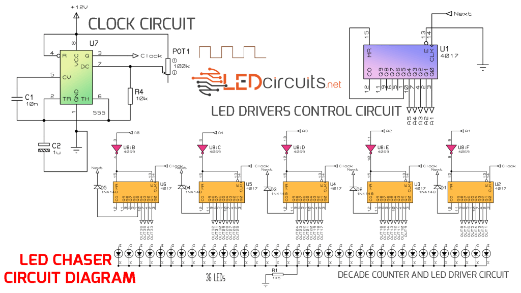
I built the clock circuit using the 555 integrated circuit. On other topics, I explained in detail how it works so I won’t describe it again.
Next part is CD4017. The CD4017 is a 5-stage Johnson counter IC and has 10 outputs. The operating voltage is between 3-20 volts.
Q0-Q9 counts in decimals according to the pulses applied to inputs 4017, Clock (Pin 14), Clock inhibit (Pin 13), and Reset (Pin 15). By connecting the Carry Out output to other CD4017BE ICs, you can continue counting in the decimal system.
When Clock Inhibit (Pin 13) and Reset (Pin 15) pins are in logic 0 state, if clock pulses are applied to Clock (Pin 14), outputs Q0-Q9 are activated respectively.
The counter stops if the Clock Inhibit input becomes logic 1 while clock pulses are applied to the Clock input. Similarly, if the reset input changes to logic 1, the counter is reset and the outputs are cleared.
We have another integrated circuit next..
CD4069 is a hex inverter. The 4069 ic, which is very simple to use, transfers the logic level applied to its input in reverse to its output. For example; If we connect logic 1 level to input then we will get logic 0 from output. Conversely, when the input is logic 0, the output becomes logic 1.
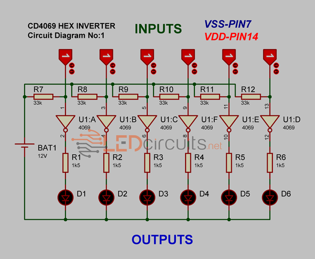
As seen in the circuit diagram, 4069 ic has 6 inverters. I set all the input sections to logic 1 and pull-up with 33K resistors. Each input has a separate output. I connected the outputs with a 1.5k ohm current limiting resistor to the anode terminal of the LED. I connected the cathode terminal of the LEDs to the (-) terminal of the battery.
If we run the test circuit, none of the LEDs light up because logic 1 applied to the input is inverted as logic 0 at the output. If we connect the input section to logic 0, we get a logic 1 level from the output.
How it Works
Yes, you have learned how the CD4017 and CD4069 integrated circuits work. Now I will explain in detail how the led chaser light circuit works.
There are a total of 6 CD4017s in the circuit. I run the LEDs of the led chaser light circuit with 5 CD4017s. The 4017, which has the U1 code, controls the sequential operation of the other 4017 integrated circuits.
Even though CD4017 is a decade counter, I can use only 8 outputs.
When the circuit is energized and run, the Q0 outputs of the CD4017 integrated circuits become logic 1 level. Since NE555 operates in astable mode, it generates clock pulses whose duration can be adjusted with the trimpot.
The clock pulses are connected to the clock input pin of the other CD4017 integrated circuits, except U1. Clock inhibit and Reset inputs are connected to the output terminals of the CD4069 integrated circuit. This way, we can control which CD4017 counter will be activated. So how do we control?
Of course with the U1-4017 ic
When the circuit is energized, the Q0 outputs of all 4017s come to logic 1. The Q0 output of the U1-4017 integrated circuit is logic 1, the other outputs are logic 0.
Logic 1 is inverted with the 4069 IC and becomes logic 0, thereby activating the U2-4017 IC.
With the clock pulse generated by the NE555, U2-4017 continues to count. When the Q9 output is active and logic level 1, a pulse is sent to the U1-4017 integrated circuit via D1 diode, and the next output is activated.
When the Q1 output of U1-4017 becomes logic 1, the U3-4017 integrated circuit starts counting. In this way, after completing the last CD4017 count, the Q5 output of U1-4017 goes to logic 1, and U1 is reset. Then it continues to count again and to activate the 4017s of the LEDs in sequence.