NE555 oscillator – 555 timer chip can achieve clock pulse, time delay circuit, or PWM (square wave) using only a few passive components.
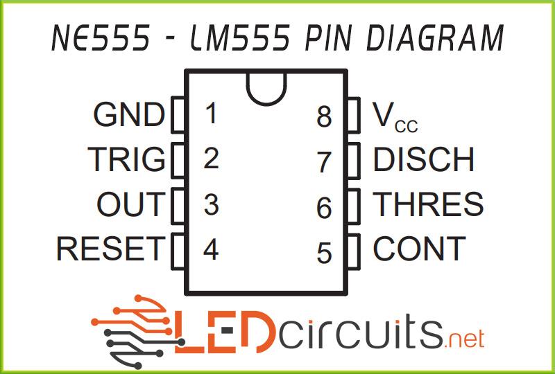
The pin diagram of this integrated circuit with a total of 8 pins appears below;
HOW IT WORKS?
The 555 timer ic can be operated in two different ways;
- Monostable
- Astable
The common feature of the two operating system is that the capacitor C changes as it charges and discharges over the R resistor, creating a square wave (PWM) from the output pin.
Monostable Multivibrator
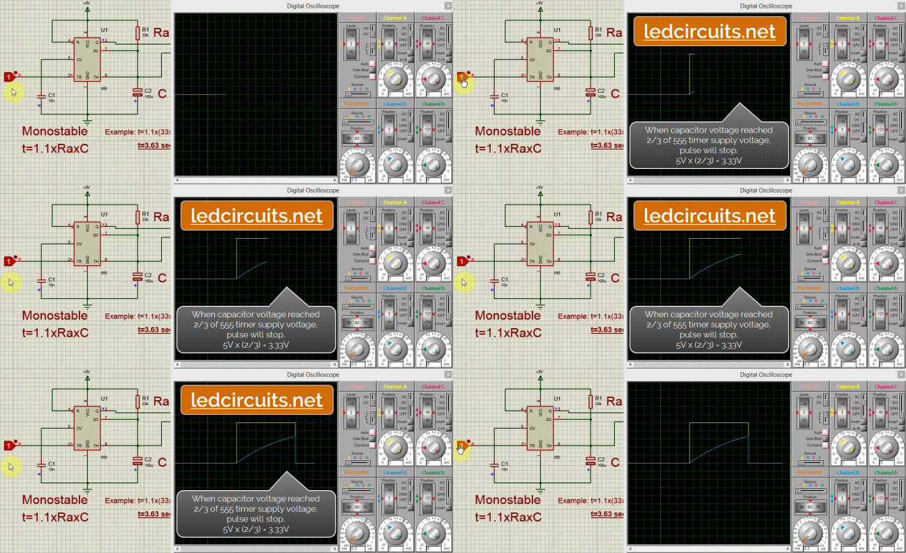
Briefly, the logic of work is as follows;
If the voltage applied to the trigger input (Pin 2) of the 555 oscillator is less than 1/3 of the supply voltage (Vcc), a pulse occurs at the output (Pin 3).
The pulse ends when the voltage of the capacitor (C) equals 2/3 of the supply voltage.
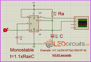
- Duration of the pulse is determined by the formula below according to Ra and C values.
![555-timer-circuit]() Astable Multivibrator
Astable Multivibrator
In this mode, trigger input (Pin 2) and threshold (Pin 6) are connected. Thus, unlike monostable circuit, NE555 works as a self-triggering multivibrator. Capacitor C is charged through resistors Ra and Rb while it is discharged through resistor Rb.
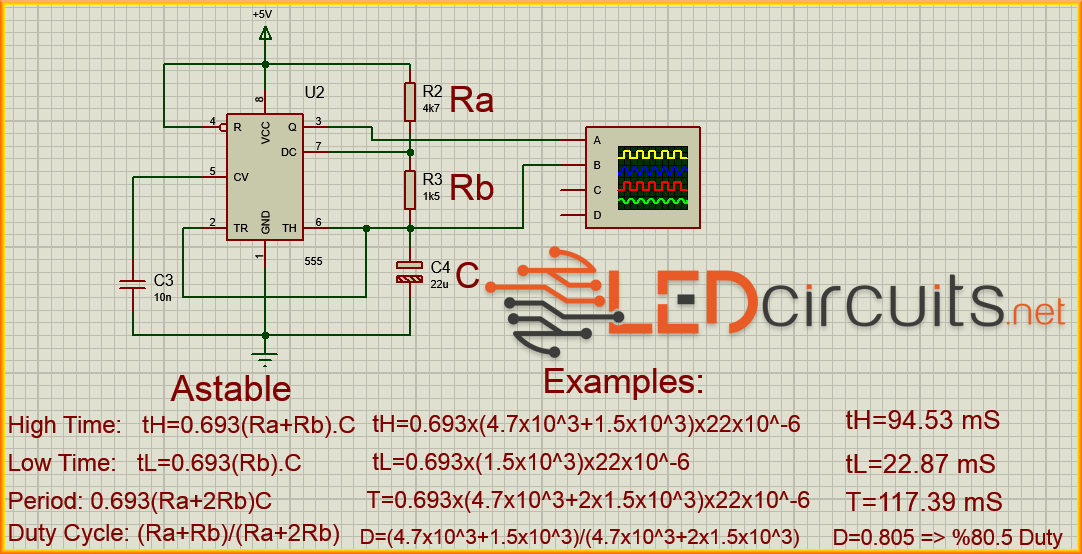
- You can calculate the duration of the signal received from the output (Pin 3) according to the following formulas according to the values of Ra, Rb and C.
Low Time : tL=0.693(Rb)C
Period : 0.693(Ra+2Rb)C
Duty Cycle: (Ra+Rb)/(Ra+2Rb)
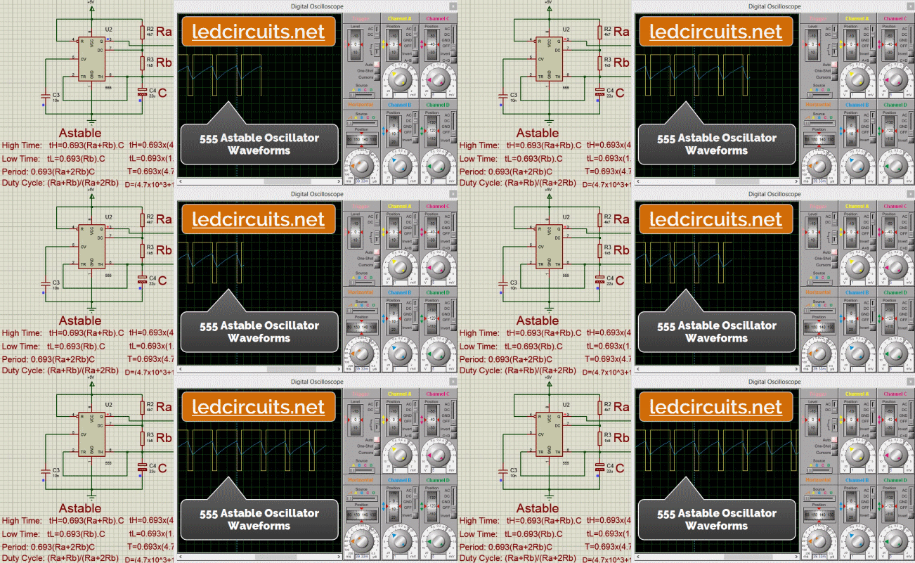 In the sample calculation;
Ra=4K7 = 4700 Ohm
Rb=1K5 = 1500 Ohm
C=22u = 22 micro farad
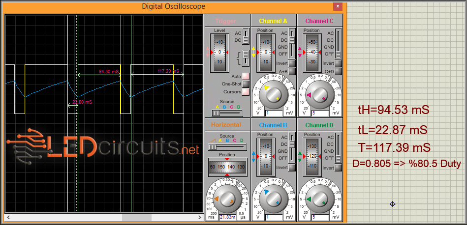
According to these values, the following oscilloscope image is formed.
