
NE555 & 74HC595 PROJECT
List of Materials:
4x 74HC595 (Shift Register)
1x 7805 Voltage Regulator
2x 10K 1/8W Resistors
2x 1K5 1/8W Resistors
32x 470R 1/8W resistors
1x 50K Potentiometer
32x 5mm LEDs (4 pieces white – 12 pieces pink – 16 pieces green)
1x BC237 NPN Transistor (or similar low power NPN transistor)
1x 2.2uF 16V Electrolytic capacitor
1x 1uF 50V Electrolytic capacitor (16V or higher voltage)
1x 10nF Ceramic Capacitor
4x 100nF Ceramic Capacitors
1x 5x10cm Prototype PCB Board
Preparation for the Circuit
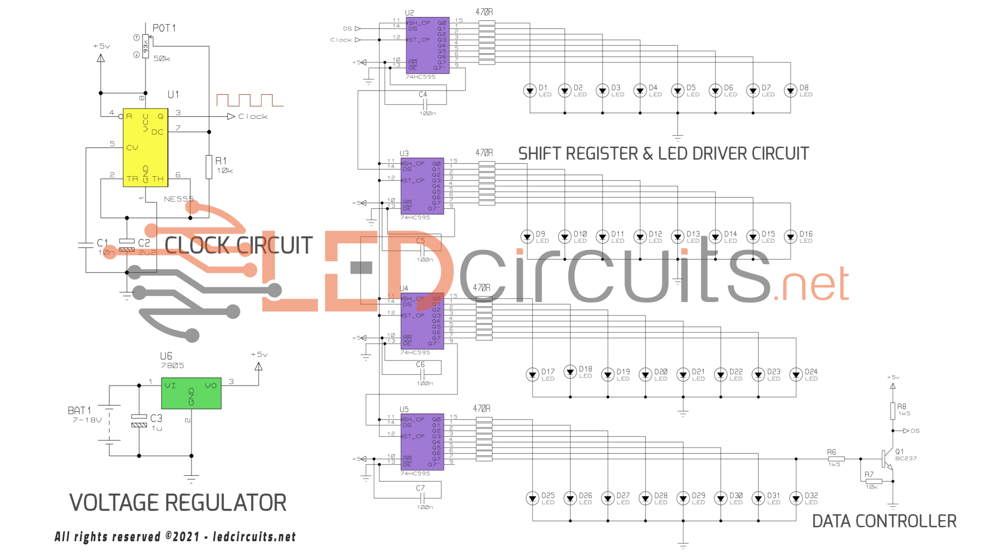

Our LED animation circuit consists of 4 parts. These are;
- Clock circuit
- Voltage Regulator circuit
- Shift register with led driver circuit
- Data control circuit
I built the clock circuit with NE555. It produces clock pulses, which we will use for 74HC595. To do this, we will run the 555 in astable mode and control the animation speed with the 50K ohm potentiometer.
Another part is the voltage regulator circuit. We will be using the LM7805 linear voltage regulator for this job. 7805 is a widely used voltage regulator and we can make it ready by using 1 filter capacitor as shown in the circuit diagram. Thus, we will reduce the input voltage between 7-18V to 5V and run our circuit. Although the maximum current value required by the circuit is 0.20A (200mA), it can provide 1A current when used with the heat sink.
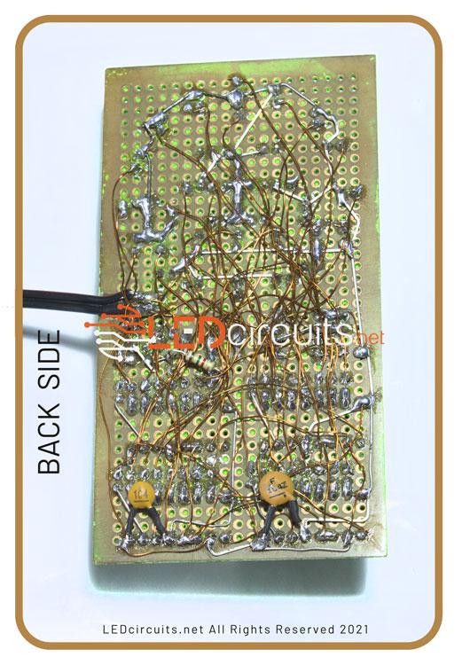
I used the prototype PCB board and 0.25mm enamelled copper wire for soldering.
The next part is the shift register circuit… I used 74HC595 for this operation. 74HC595 is the serial input parallel output (SIPO) shift register. The 74HC595, which has a total of 16 pins, has 8 output pins. It can operate with a voltage between 2-6V.
While working with 5 volts, a maximum of 6mA current can be drawn from each channel.
Can run at 13ns scanning speed.
How it works
NE555 produces a square wave signal by operating in astable mode.
With the generated square wave, the DATA is sent to the 74HC595 and transferred to the output by shifting once.
What is data?
When the NPN transistor is the cut-off region, the Data is Logic 1 otherwise, when it is in the active region, data is Logic 0.
Once the circuit is powered up, all pins of the 74HC595 are Logic-0, so the transistor is in the cut-off region.
Data Logic-1, is sent to the 74HC595 and the LEDs start to light with the signal generated by the NE555.
When the last led lights up, the transistor conducts and Data becomes logic-0. Then the leds start to turn off by shifting in turn.
If you have any questions, feel free to ask.. 😀